
Flashing Tasmota firmware on a Sonoff Basic to build your own WiFi switch
2020-1-3
By Sumit Maitra
Back in the days I had hoped to setup cheap SMPS, ESP8266 modules and a relay to build my custom 'wifi switches'. I had bought all the components separately, but unfortunately, time isn't something that can be purchased off the market. Thanks to other distractions in CAD, 3D Printing and robotics, this project kept getting shelved and the components never got used.
So this holiday season I decided to finally do something about home automation. I was hoping to do the following:
- Control a bunch of lights over Wifi
- Have no Cloud dependency
- Don't need ripping out existing cabling and can be easily retrofitted.
The Hardware
I initially started looking at Amazon discounted WiFi plugs but no one could say if they were easily hackable so I expressed my frustration on Twitter. Thanks to the lovely company I keep there, couple of people pointed out to me that there was something called Sonoff. Yes, that's spelled correctly, seems like an abbreviation for Switch On/Off.
These little magical devices have an SMPS + ESP8285 (on the version I got) + breakout pins + indicator LED and a Push to On switch connected to the GPIO and an input and output terminals for 220V AC loads upto 10A.
I mean what more can anyone ask for? The cost - £13.74 for a pair (with Amazon Prime, cheaper on Ebay if you wait for them from China). Honestly, in UK, you can't assemble them for cheaper if you bought disparate components (unless you buy all parts in bulk from China). Today Sonoffs are available for less than £50.00 if you buy them in packs of 10 from China.
Here is what a Sonoff basic looks like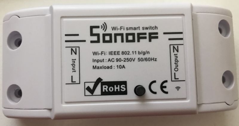

The software
Any IoT hardware is pretty useless without it's Software. All Sonoff switches work with an app called eWeLink. I haven't tried it, but the basic premise is you tie your Sonoff switches with your App and control them from the App. The server is hosted on public internet so you can control your light switches from anywhere, you have internet access.
Elephant in the room
With every IoT cloud service my first question is what happens when the internet goes down? I mean even my fancy Coax to home internet goes down when my ISP decides to reboot the Router and the router takes upto 15 minutes to reboot. So now what?
Security is another question but let's not go down that rabbit hole yet
The Sonoff Basic does come with a tiny push button that you can push to signal On/Off. However, the Sonoff Basic isn't always meant to be installed where a traditional switch is. If you are retrofitting these in, you are likely to place it near the light/fan/appliance you are planning to turn on/off with. Hence my basic requirement is every bit of IoT hardware should have software that is reachable without access to the internet (Bluetooth, Local WiFi, ZigBee, RF 433 remotes, etc.)
Customising ESP82** firmware with and open source one
Sonoffs popularity stem from the fact they are hackable. They come with four (or five) pin headers, all you need are some header pins and an FTDI programmer to flash them, and write custom code via the Arduino.
Now before you start hacking your own switch code, consider looking around, it is very likely someone in Open Source community has built all or significant bits of things you need. Enter Tasmota!
Open source home automation servers
Once you install Tasmota (as we see below) you need some kind of a hub that helps you communicate with your Wifi switch. Addressing that elephant in the room are Open source home automation servers like OpenHab and Home assistant.
I will also walk through setting up OpenHab to control your Sonoff later in this post.
Installing Tasmota firmware for ESP82xx based Wifi switches
Today I am only going to walk through flashing a Sonoff with Tasmota. Once I am done exploring all the features it offers I may come back and mess around with the code for some additional features in future.
Note: I am flashing the firmware using my Debian 9 desktop. OSX couldn't detect my FTDI programmer, I suspect it is the Catalina update that buggered it. I am a little vague on how this thing works with Windows.
One time:
Step 1: Download latest Tasmota binaries from their releases folder on Github. At the time of writing this was version 8.1.0 (Doris Release). I downloaded tasmota.bin. You can download various custom language versions if it helps.
It is a good idea to rename the binaries to the version you downloaded e.g. tasmota-8.1.0.bin. That way you can keep track of which version you downloaded and installed last.
Step 2: Install ESPTool. From the Github page, ESPTool is
A Python-based, open source, platform independent, utility to communicate with the ROM bootloader in Espressif ESP8266 & ESP32 chips
I should add it does work with ESP8285 as well.
Install ESP Tool using Python package installer
pip$pip install esptoolThereafter the instructions say just type
esptool.pyand it should work, but it didn't quiet work for me. I had to provide it with the absolute path of the install folder to access the binaries. Mine was installed at~/.local/bin/esptool.py. Possible a symlink wasn't created when installing on my version ofpip.
Now you have the tools ready, let's setup the Sonoffs
Make sure, if your FTDI programmer has voltage selector you set it to 3.3V and not 5V. 5V will damage the ESP82** beyond repair.
For every Sonoff you have:
Step 1: Solder a header onto the Sonoff to plug-in your FTDI programmer. As shown in the image below I have soldered a female header into the 4 exposed pins. The location of the header pins have varied over time but they have been there nevertheless. Flip the board over to see which pin is what.
 As you can see in my board, they have not punched through the IO2 hole, which I believe is a GPIO pin, we shall come back to that later. For now, pick a header size appropriate to your board (4-pin/5-pin).
Step 2: Use some jumper jerky to connect FTDI programmer to Sonoff.
| Sonoff | FDTI programmer |
|---|---|
| GND | GND |
| TX | RX |
| RX | TX |
| 3.3V | 3.3V (don't forget to set your FTDI programmer to 3.3v it supports 3.3v and 5v) |
Step 3: Plugin your FTDI programmer to you computer and identify it using the following command:
$ ls -l /dev/tty*
This should give you a (long) list of tty devices and your FTDI programmer should start with USB or usbmodem etc.
Mine simply got listed as /dev/ttyUSB0

Step 4: Set the Sonoff in bootloader/programmable mode.
My Sonoff was wired to the programmer as follows:

After you have double checked the connection and voltage between your FTDI programmer and Sonoff, press down the button on Sonoff as you plug the programmer into the USB port of your Computer. Keeping the button pressed when powering up, puts the ESP8282 into bootloader mode.
Once it is in bootloader mode, change directory into where you downloaded the Tasmota firmware binaries.
Flash the ESP using the following command:
~/.local/bin/esptool.py -p /dev/ttyUSB0 write_flash -fs 1MB -fm dout 0x0 tasmota.bin
I am not sure why I had to use the absolute path of esptool.py, quite possible because I didn't restart all my terminal windows.
After about 30seconds of TX/RX leds flickering on the programmer, esptool will announce that the firmware has been flashed. It does give you a progress on the console as well.
Connecting the Tasmota-Sonoff to your Wifi network
Now that you have flashed the Sonoff, unplug the programmer's USB from the computer and plug it back in to reboot it. No need to keep the button pressed down now. When the Tasmota-Sonoff boots up for the first time, it presents itself as a Wifi hotspot, and when you connect to it, it will bring up a form like the following:

The basic thing you need to remember is to setup your Wifi SSID and password correctly. You can either type in your SSID or use the "Select wifi networks to pick your WiFi".
Another thing to note is, if you ware on OSX as soon as you connect to Sonoff's hostspot a dialog will open automatically. In other systems this may not happen. In that case navigate to 192.168.4.1 in a browser to get the above page.
Finally, notice the Hostname field. It is a set of placeholders. You can change it to something more recognisable like 'myroomdesklamp' or 'livingroomtv' or whatever your naming convention is for your IoT devices. That way it is easier to access once it reboots.
Once you save these, the Tasmota-Sonoff will reboot on its own and instead of being a hotspot, connect to your Wifi.
To toggle the Tasmota on or off, you have to go to it's 'home page'. This will be at http://[Hostname].local
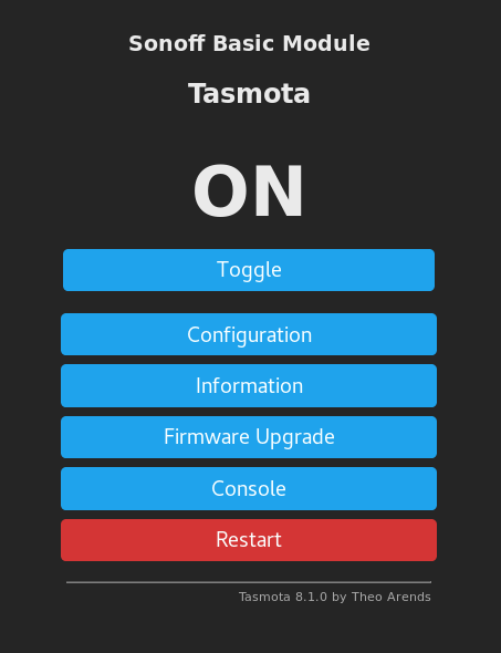
Use the toggle button and you should hear the relay click on and off.
Getting started with MQTT
While setting up an MQTT server or a full fleged OpenHAB setup is out of the scope of this article, I'll leave with a sneak peek on what you can do when you have an MQTT server setup.
If you go to the "Configuration" page from your device's home page you will see the following options:

Click on Configure MQTT to get to this page, where you can setup the
- MQTT Server Hostname or IP Address : This will be where you MQTT server is, IoT platforms like OpenHAB setup on for you.
- You can setup user name/password for the Sonoff to connect to the MQTT server (if your MQTT server uses authentication)
- Lastly, the
Topicand theFull Topicallow you to setup a unique MQTT topic for this Sonoff. Topics are a bit like RSS feeds, that your MQTT server listens to or sends information out on. More on MQTT at a later point.
For now, you have a WiFi relay that you can place between your mains device and a powerline, and you can control it wirelessly. Remember to be safe when dealing with mains. Breaker switches are your friends, use them to turn off the line before you go experimenting.