Getting started with PiWars!
2017-10-26
By Sumit Maitra
... and how not to apply for it! Beginning of the month we found out our maiden application hadn't made the cut for PiWars 2018. Made me sad, momentarily, but it faded away fairly quickly. We were too invested in this to not do it. Sadly for us our commitment and intensity wasn't evident in our application.
One re-look at the application and it was obvious, organisers didn't have to think much about putting it in "not serious" basket!
So lesson learnt - * When a PiWars application opens, remember it is not first-come-first-serve. Don't be in a mighty hurry to hit Send on your application.*
Take your time to read through the challenges, formulate a rough plan in your head or on a notepad on how you think you will approach the challenges. Do some background research on what it takes to attempt all the challenges.
It is possible you will have to learn a lot before you are done, list those in a "to learn" column and say it out loud. If you are a first-timer at PiWars (like me), do lots of homework. Dig up all the past videos, blogs and pictures about PiWars.
Finally, find like-minded Roboteers nearby and form a team/community if you are not applying on behalf of one already! RaspberryPi is all about community and education, more the merrier.
So if I were to re-apply - "Proposed robot details" section of my application would be something like this:
We are planning to build our robot using a RaspberryPi 3 and a ThunderBorg motor controller at its heart. We plan to use the motors that come with the MonsterBorg (or similar).
The chassis will be custom designed and 3D Printed. At the end of the challenge we'll make all our designs open source for everyone to view/share/improve. We have a rough sketch of how it will support front-wheel-steering. This, we hope, will give a bit of uniqueness to the drive system of an otherwise standard four-wheeled robot.
The bot will be equipped with four (or more) Ultrasonic sensors for distance sensing to help it navigate the Speed challenge and the Maze challenge. We've looked up past challenges and found managing timing for Ultrasonic sensors in software is tricky so we are planning to use dedicated hardware to capture the sensor data and pass it on to the Pi. Looking around, we found an Arduino powered project that does 360 degree coverage using 8 sensors. However the UltraBorg by PiBorg supports four HC-SR04 sensors plus four servos with independent power supply. It is an I2C board that supports daisy chaining so if we found need for more than four sensors we could get two of them working in tandem. The additional support for servos will come in handy for the steering and an attachment we have in mind for the 'Over the moon' challenge.
For the speed challenge, previously, a wall-hugging algorithm looking at only the left or the right wall was enough to keep it straight. Introducing the narrowing of track, steps up the challenge and we hope to be able to use distance on both sides combined with the steering capability to keep us centered.
With four distance sensors and a independently steerable robot, we hope to perfect a routing algorithm that enables the robot to navigate the maze challenge fairly independently. However, if we encounter issues we may resort to the visual cues that are being offered and use OpenCV.
For 'Over the moon' challenge we will need at-least one camera. We plan to mount the camera on a pan tilt mechanism (we already have a un-used Pan Tilt hat kit from Pimoroni) and drive it via the UltraBorg's servo drivers. We don't know yet, there is a chance 180 degree movement is going to be enough to capture all the four corners of the challenge pit. If it doesn't we will have to re-work the image-capture system to have two cameras facing away from each other and will be easily able to cover a 360 degree view. We are new to OpenCV but have looked at the possibilities and we hope to be able to trace out the position of the 4 balls and workout an optimal run during the first parse. The second and third parse won't require the route calculation so we hope our best times are in these runs. We would like the capture unit to be an independent PiZero talking to the mother ship over USB.
If we gain enough OpenCV experience we may use the camera as a backup for centering in the line challenge as well.
The Duck shoot challenge seems very interesting given the complexity of building a projectile launcher. We haven't thought this through yet, but we saw <a "Nerf Tank by David Pride" rel="nofollow" href="https://www.raspberrypi.org/blog/nerf-gun-tank-fred-209/">David Pride's nerf dart launcher and we do have a Nerf gun that can be sacrificed. We will probably follow David's lead for this one.
Tada!
Well, that definitely looks better than what I said in the application:
I am currently waiting eagerly for the MonsterBorg kit to be delivered. If selected, our Robot is likely to be based on the ThunderBorg board and a Raspberry Pi 3.
We have a 3D Printer so the chassis is likely to be 3D Printed.
Yeah, that's pretty embarrassing alright!
Mind you, most of the things I wrote above are stuff I found out after I submitted the application and before the last date of submission. So even if you start thinking about your new Robot after the Applications have opened, you have enough time to think through your approach and form a coherent plan. It should reflect in your application.
Will the additional details ensure selection, NOPE!
Remember, the organisers have an un-enviable and fairly subjective task of picking teams from the hundreds of applications. If you don't make it, don't despair, continue with your experimenting and learning. Talk about what you learn and where you get stuck, share it with people via, blogs, talks and workshops. Remember, PiWars is more about community and education and not to do with cut-throat multi-million pounds professional competition (I can hear some of you ;-)...)!
Go to the actual event anyway, it should be a lot of fun. You can get spectator tickets here.
On to robot-making
With the application out of the way, and having decided the only way was forward, we decided to get started with the Chassis.
The chassis
With the MonsterBorg delivered, our primary motors and motor drivers were pre-decided. The MonsterBorg is a monster all-right. You cannot use its super neat aluminum chassis along with the default tires. The resulting bot is wider than the allowed width of a A4 size paper. So step 1 was to build a custom chassis.
Using Tinkercad
Tinkercad is a really neat online/web-based 3D Design tool. It is super easy to get started, just follow their online Tutorials for an hour or so and you are off.
I faced a problem with Tinkercad straight off the bat. The default build plate on Tinkercad isn't big enough to support the A4 size robot. Neither was my 3d Printer. With a 190mm square usable build plate the best I could hope was a two piece chassis.
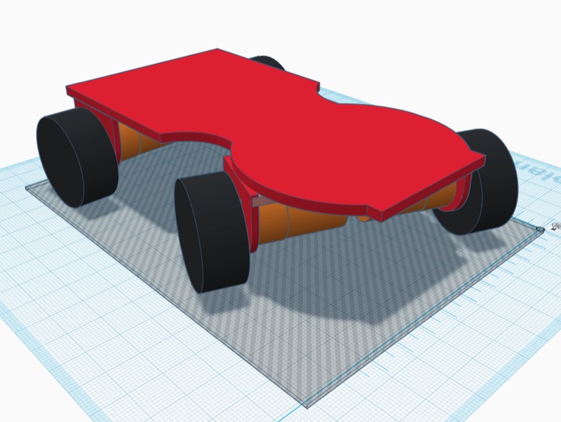
To keep things proportional I started with a 1/2 sized model in Tinkercad (1/2 height, 1/2 width and 1/2 length). Here is a sneak peek of the scaled model.

Modeling the pieces
The way I (3D) model a piece is to first create the items that the model is going to support. For example if I am building a Pi Zero case, I like to have a 1:1 model of a RaspberryPi Zero that I can then use to build the case around.
I wanted to start with a monocoque design for the chassis. A metal monocoque shell is pressed into shape against appropriate dies. I decided to carve it out of solid (virtual) blocks. This meant designing the bits to carve out separately. First on the list were the motors :-)
The ThunderBorg Motor
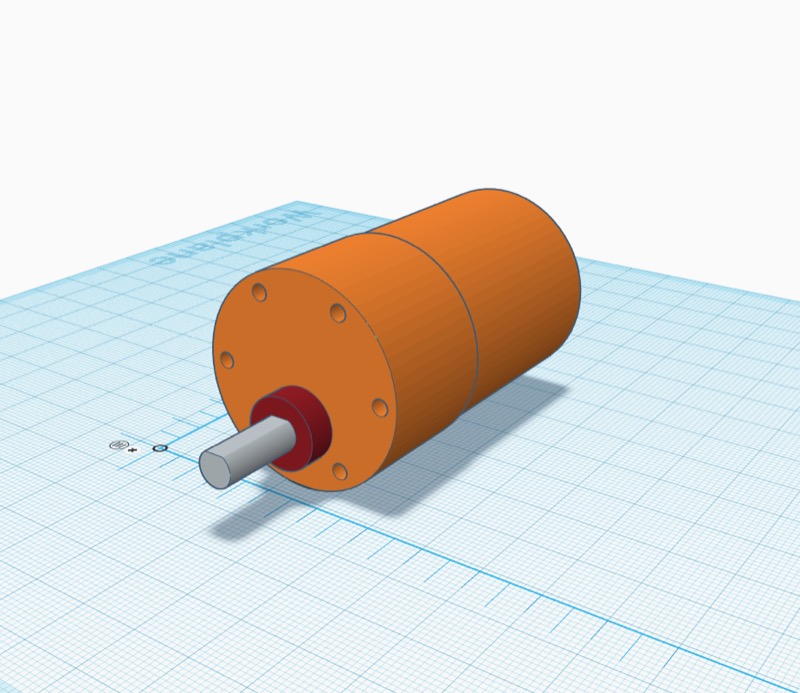
In this case the first thing I needed was a fairly matching replica of the giant ThunderBorg motors! With a set of Digital Vernier Calipers I had the measurements done quickly and ended up with this
Building the motor accurately enables me to put it in the rest of the design and 'subtract it'. It also allows for a better understanding of how things fit in and where. For example, I wasn't sure if I could fit the ThunderBorg motors and the Diddyborg wheels.
The Motor mount
With the motor ready, the motor mount was 'relatively easy' to design. But I didn't want to use it directly in a single block without testing if the motor would fit. So I designed a small piece that just had the appropriate holes to hold the motor. This nondescript little thing too 4 attempts to get bang on target. However, advantage of building it separately first was I spent only about 30 minutes one each incorrect print job, instead of the 6.5 hours it took to print the whole rear section.
The Rear section
Once the motor-holder was ready, the rear section was easy. I copied the base from the above scaled model, increased it to correct proportions and then chopped off the front half using a big transparent box.
Next I placed two motors on two sides and put the holders at appropriate places so that the mounting holes all lined up correctly.
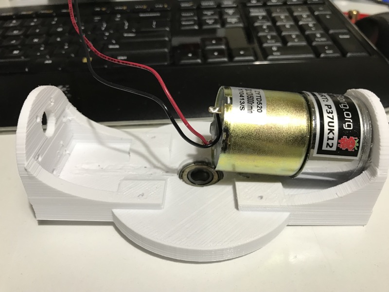
Finally, there was a gap between the chassis plate and the motor. A metal frame is rigid enough but a plastic one isn't, so I built a platform to support the motor and have provision for a u-clamp to secure it (and take weight off the motor holders). To increase the area of contact between vertical and horizontal edges I tapered all joints as you can see. The actual printable section without the motors looks like this

The 'joiner'
The keen-eyed would have noticed some additional holes in the base of the rear section above. Thing is if you break something into two, you have to put it back as well. I considered various ideas like a door-hinge design to bolt the pieces together, only glue, glue and dovetail joint or glue and box joint. In the end, I went with a glue and support. I knew I had to fit a RaspberryPi firmly on the chassis. Using the underside of the frame for joining the chassis was kind of 'easy way out'. So I went on Thingiverse and found a nice RaspberryPi Chassis and then imported it into Tinkercad. Placed the base on the chassis and used the mounting holes to put in the screw holes.
The Front Section
The Font Section had three major parts: The Chassis Base, the Steering + Wheel Mount and the Sensor mount. Ideally the sensor mount is a part of the Wheel mount but I kept is separate so we could swap it for a 'grabber' attachment when using in non-autonomous mode.The Base - I just moved the transparent box to the rear and whatever was left was the front section. The little fidget-spinner inspired center section is actually for the mounting a 8x22x7 ball bearing. The bearing is going to be embedded in the Steering+Wheel mount allowing the steering to move easily. Atleast that is the plan. These are completely uncharted territories for me, so I am taking it as it comes.

The Steering + Wheels mount - I created motor mounts similar to how I had done for the rear of the case and added a 22mm hole in the middle for the ball bearings. Can you spot the design defect?
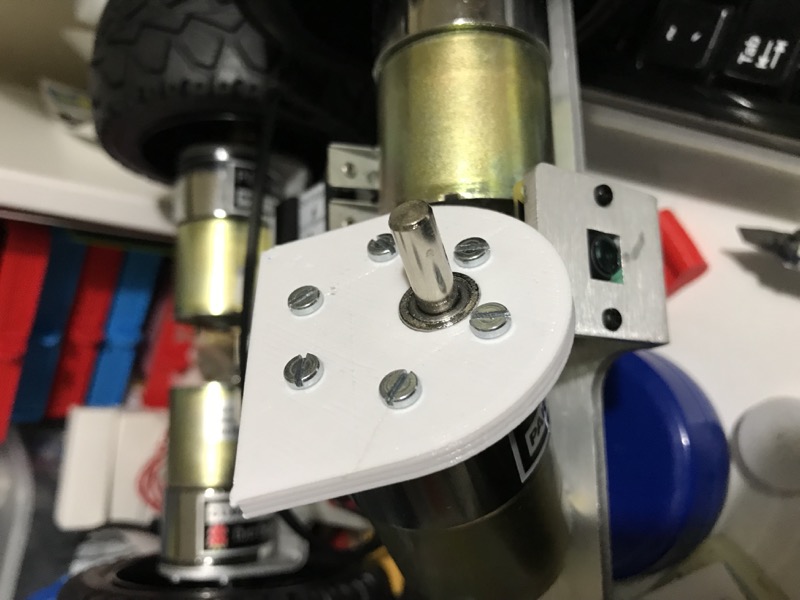
 The peach color bleeding through the red is an indication that there isn't enough space for the motor to fit in. I ended up with motors that mounted like this:
 Took a fair amount of filing to get it fitted eventually. I'll adjust and reprint later.
The Sensor mount - Last bit was the Ultrasonic sensor mount. I wanted it as far ahead as possible because I want it to detect the turns in the maze quickly enough. I am hoping, mounting it on the steer-able bit will give a more accurate reflection of current position and future direction. Given I have never worked with Ultrasonic sensors this is all a guess. We will know once we get it in action.
This is the second iteration, and again, I built a separate HC-SR04 sensor mount design first and printed it out. Once I was happy that it fit the sensors well enough used it in the final mount.
That's about all the bits I have designed so far. Apart from the issue with the front motor mount, they fit well.
Getting started with the Electro-Mechanicals
3D Design and Printing can be a lot of fun in itself. But that will only give you a static bot. You need to bring together all the electro-mechanical bits and tie it up with software to give it life.
Next step was to test if the UltraBorg and the ThunderBorg would play nice with each other. Both being I2C devices I did not anticipate any trouble and turns out, after you have read through the documentation of the UltraBorg and ThunderBorg, it is no trouble at all. Look for their daisy-chaining diagrams with the colour coded pin markings. If things don't work at first, wiggle the wires.
Here is what my wiring looks like.

During the first test, I was powering the UltraBorg from the Pi itself because it was only using the HC-SR04 sensors. However if you want to test with Motors, take out the jumper on the UltraBorg and power it from a separate power source. I am still undecided if I should use a separate Lithium Ion + Adafruit Powerboost combination or tap from the 12V output of the ThunderBorg and use a Hobbywing UBEC. More about that in the next post.
Once tested, I bolted the joiner to the top of the chassis and put the Bot together.

Unfortunately, I didn't have the steering servo while doing the design bits, so up until this point, I had 3 Ultrasonic sensor readings, 4 controllable motors tied to a motor controller, all tied to a Pi but no steering. I am currently working on the steering motor mount. Once it is ready, I will start with a Rock Candy controller. I will probably have a XBox controller in the standby too. That's when the fun will actually start. Hopefully an update in another couple of weeks! Till then keep robot hacking!
Until such time here are a few random images of our progress.
P.S. If you are a part of PiWars then you should probably join the Discord group run by Tom Oinn. It has an enthusiastic bunch on roboteers who have either participated in a PiWars before or are signing up this year. It is a very nice place to ask any question.


