PiWars 2019 Diary - Motors, Brackets and GPIO
2018-11-30
By Sumit Kumar Maitra
Many apologies for the delayed update, I have been failing at doing detailed blog posts rather badly, but here we are. It has been more than a month now and we have made quite a bit of progress from last time, but nothing is readily visible because the bot still doesn't move on the ground.
In the last month (and a bit) we have managed the following :
- We have verified that our adjustable suspension/ground clearance system works.
- We managed to validate that the steering idea will also work once we have hooked up the final link to the rather OTT looking steering mechanism I've designed.
- We have treaded lightly towards controlling DC Motors using the Dual H-Bridge via GPIOZero wrappers.
- Quite a bit of time was spent on trying to get various parts of the bot on the chassis. This meant some very long print jobs (that failed once) to build a battery box, a set of brackets to hold the Cytron Motor Controller, and some shims to ensure there is enough gap between the controller and the battery box as both of them are on the undercarriage of the bot.
- On the software front, the BotHub is now able to communicate with the other Pi directly over bluetooth.
- And among other things, I figured out there is a thing called 'solder tip tinning' and if you get this magical thing, you can restore all the soldering irons you have thrown away because you couldn't find suitable tips after they had oxidised 😁. Big time hat tip to Neal Oldmeadow for that one.
Controlling servos with 4Tronix Piconzero
Adjustable ground clearance
I tried to get the adjustable ground clearance system working first because I wanted to know if that idea actually is workable with the hardware and chassis design I had. Turns out it works like a champ.
Here is a quick action peek of the first attempt. Since then, I have updated the attachment a bit to better utilise the circular path of the the levers.
As you can see, two beefy servos push down on a platform raising the chassis and in effect anything that's tied to it. However, 'ground clearance' doesn't really change because to start with we don't have anything that's below the lowest point in the bot that's currently the motors. As you will see later this changes when I start mounting various robot bits.
The up and down motion is controlled by a 4Tronix Piconzero. A Piconzero is an excellent little board that uses an ATMega microcontroller to add on to a Pi's capabilities. It supports 6 GVS outputs which means we can control upto 6 servos with it. It can also control two brushed DC Motors. Best part is, you power the motors via the 5V Micro USB connector. This separates out power to Pi and Power to Servos. It has another power port that you can use to power the DC Motors upto 12V if you want. But I believe you can't use both at the same time because you have to set a Jumper on the board to select 12V or 5V supply inputs. My Servos were 6V servos, so I am slightly undervolting them at 5V, but they pack enough punch even at that.
Right now I have a simple but of code that moves the servo arm up and down resulting in the lever pushing down/up on the platform.
import piconzero as pz, time

#======================================================================
# Reading single character by forcing stdin to raw mode
import sys
import tty
import termios

def readchar():
    fd = sys.stdin.fileno()
    old_settings = termios.tcgetattr(fd)
    try:
        tty.setraw(sys.stdin.fileno())
        ch = sys.stdin.read(1)
    finally:
        termios.tcsetattr(fd, termios.TCSADRAIN, old_settings)
    if ch == '0x03':
        raise KeyboardInterrupt
    return ch

def readkey(getchar_fn=None):
    getchar = getchar_fn or readchar
    c1 = getchar()
    if ord(c1) != 0x1b:
        return c1
    c2 = getchar()
    if ord(c2) != 0x5b:
        return c1
    c3 = getchar()
    return chr(0x10 + ord(c3) - 65)  # 16=Up, 17=Down, 18=Right, 19=Left arrows

# End of single character reading
#======================================================================

speed = 60

print "Tests the servos by using the arrow keys to control"
print "Press <space> key to centre"
print "Press Ctrl-C to end"
print

# Define which pins are the servos
pan = 0
tilt = 1
#grip = 2

pz.init()

# Set output mode to Servo
pz.setOutputConfig(pan, 2)
pz.setOutputConfig(tilt, 2)

# Centre all servos
panVal = 90
tiltVal = 90
pz.setOutput (pan, panVal)
pz.setOutput (tilt, tiltVal)

# main loop
try:
    while True:
        keyp = readkey()
        if keyp == 'w' or ord(keyp) == 16:
            panVal = max (0, panVal - 5)
            tiltVal = panVal
            print 'Up', panVal
        elif keyp == 'z' or ord(keyp) == 17:
            panVal = min (180, panVal + 5)
            tiltVal = panVal
            print 'Down', panVal
        elif ord(keyp) == 3:
            break
        pz.setOutput (pan, panVal)
        pz.setOutput (tilt, tiltVal)

except KeyboardInterrupt:
    print

finally:
    pz.cleanup()
The above code looks like a lot, but most of it is for handling keyboard entry. This is adapted from 4Tronix samples, viz. servoTest.py.
The main loop simply waits for Up/Down arrow keys or w/z keys to move the lever up or down by rotating the servo 5 degrees at a time. In the final code I may choose a finer degree of control by moving it in even smaller units of rotation. It also centers the servos when you press spacebar.
Steering mechanism
Once the ground clearance was sorted, next step was getting the steering working. Last year we had done front Ackerman steering. This year we wanted to be a little more adventurous and try Ackerman steering both at the front and back. Also unlike last year, this year our motors were on a suspension mechanism that varied in height with respect to the steering motor. So the links had to move in multiple directions as things moved around.
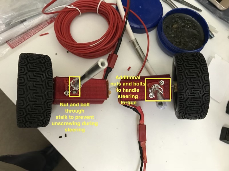
To get it work first thing we had to make sure was ensure the suspension stalk was rigid and did not pivot on the screws attaching it to the motor mount. So we had to drill additional holes and redo the bracket that attached the stalk to the mount. It ended up looking like this

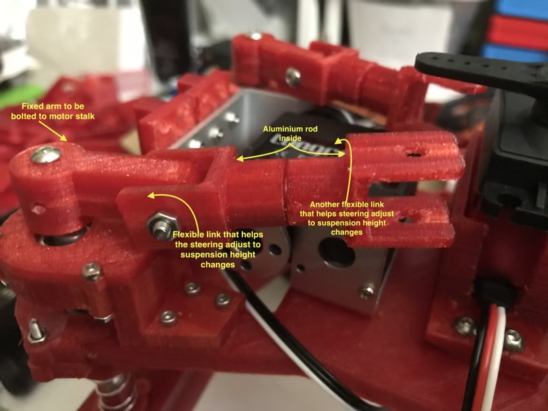
The links to attach to the steering motors were as follows:

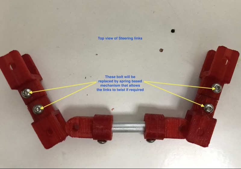
Here is a top view of all the links for front wheel steering. Similar mechanism is used for the rear wheels. I realised the mistake I made by bolting the links down, restricting twisting motion, as I was typing this post out. New idea as mentioned below is to replace them with springs in future.
The links might look dreamy but they kind of work as you can see in the video below. All I have to do it tie them to the servo horn so each small bit of motion is captured and results in wheels turning.

Here's a video showing how they may work on the bot:
With steering and suspension done, next was getting the wheels to move.
Getting started with GPIOZero and Dual H-Bridge MotorControllers
Last year we didn't have to think much about driving the bot because the software provided with Thunderborg was a very good template to start with and needed only minor tweaks to support the Controller. This year however, I went with a Dual H-Bridge controller from Cytron, which meant I had to figure out how to provide PWM signals to the Controller so that it could control the speed of the motors.
GPIOZero to the rescue
GPIOZero is a Ben Nuttall led community project that provides nice Python wrappers for all kinds of hardware that you can possibly drive via a Pi's GPIO pins.
GPIOZero has a nice wrapper called PhaseEnableMotor that you can initialise using the Pins to which your Motor Controller is connected.
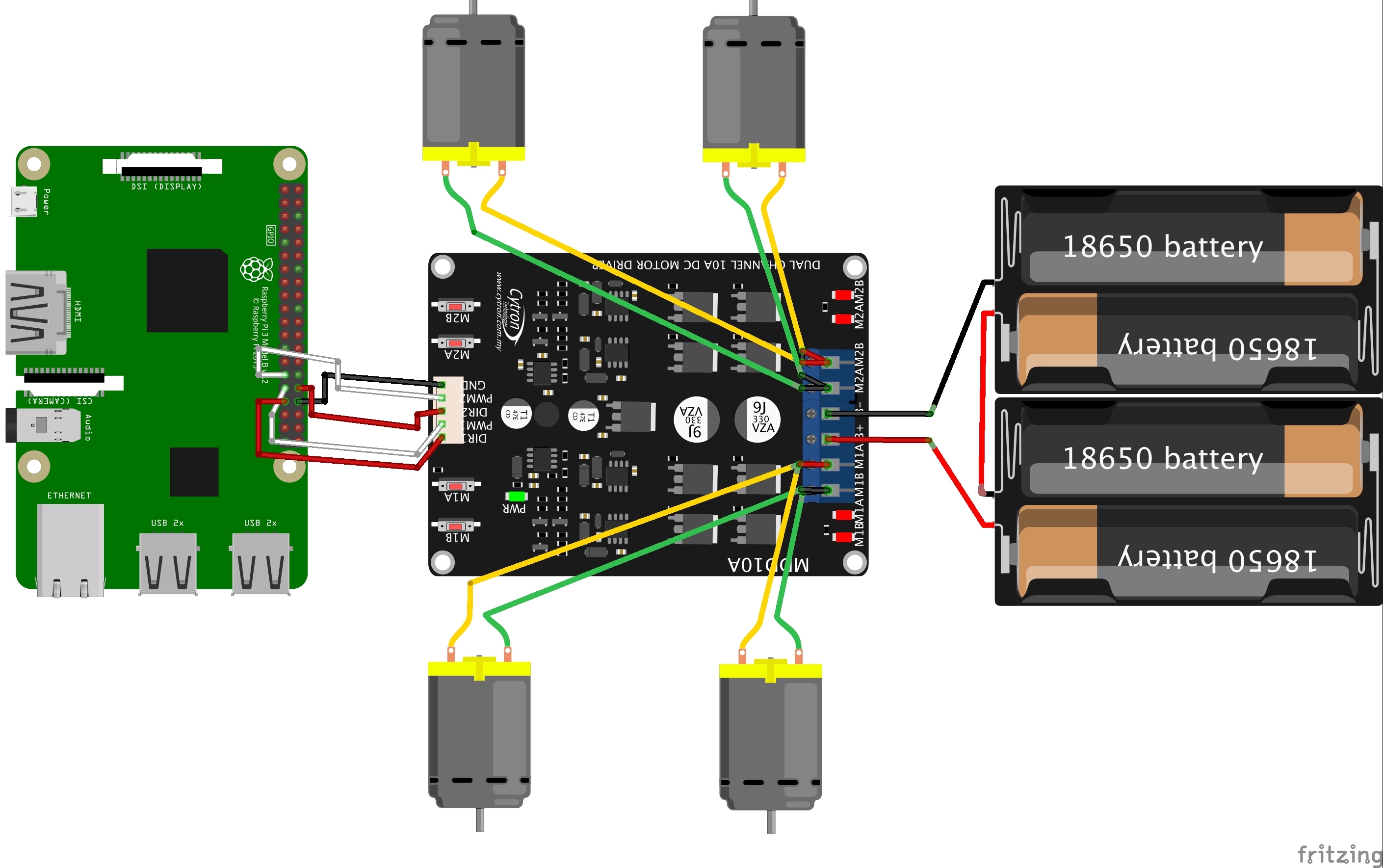
Here are the Pins on my Motor controller and how they connect to the Controller Pi.

Essentially here's how the Pins are connected
| Pi GPIO | Cyton driver | |
|---|---|---|
| BCM 6 | DIR1 | |
| BCM 13 | PWM1 | |
| BCM 5 | DIR2 | |
| BCM 12 | PWM2 | |
| Physical 34 | GND |
Installing GPIOZero
sudo apt-get install python3-gpiozero
I deliberately install the Python3 version because I do not want to use Python2 this year at all. Official installation instructions at GPIO Zero installation
Controlling a motor
To test forward and backward movement I wrote a simple loop that increases the PWM value from 0 to 1.
from gpiozero import PhaseEnableMotor
from time import sleep

enable_pwm_white_02 = 12
phase_dir_red_02 = 5

motor = PhaseEnableMotor(phase=phase_dir_red_02, enable=enable_pwm_white_02, pwm = True)

count = 0
speed = 0

while count < 100:
    count = count + 1
    if count < 50:
        speed = count * 2 / 100
        motor.foward(speed)
    elif count == 50:
        speed = 0
    else :
        speed = (count * 2 - 100) / 100
        motor.backward(speed)
    print("speed: " + str(speed))
    sleep (0,25)
This was only for one motor, but I want to drive 4 motors. You do this by connecting two motors to each channel. So two motors on the left go to one channel and two motors on the right go the other channel. Here's a bit of code to drive all 4 motors at constant 25% top speed.
from gpiozero import PhaseEnableMotor
from time import sleep

enable_pwm_white_02 =  12
phase_dir_red_02 = 5
enable_pwm_white_01 = 13
phase_dir_red_01 = 6

motor_side_left = PhaseEnableMotor(phase=phase_dir_red_02, enable=enable_pwm_white_02, pwm=True)
motor_side_right = PhaseEnableMotor(phase=phase_dir_red_01, enable=enable_pwm_white_01, pwm=True)

count = 0
speed = 25/100
while count < 100:
    count = count + 1
    if count < 100:
        motor_side_left.forward(speed)
        motor_side_right.forward(speed)
    print("speed: " + str(speed))
    sleep(0.25)
Things to note:
- The Pin numbers are BCM pin numbers not the sequence of pins on the Pi.
- GPIOZero uses a 'Pin Factory' to handle low level interaction and by default uses RRi.GPIO. This also happens to be the default pin factory. RPi.GPIO provides software PWM only.
- Even though I have connected my motor to the h/w PWM pins the software is still doing s/w PWM. So basically you can stick the data connections into any GPIO pin available and adjust the BCM pin numbers in the above code.
- Beauty of the 'Pin factory' implementation of GPIOZero is, the factories are swappable. You can configure a different Pin factory that does support h/w PWM. Looks like Remote GPIO pin factory supports h/w PWM. I am going to leave that one for now, come back to it once the bot is moving.
I leave you with a video of both the ground clearance adjustment and wheels in action in one piece
Continues...
I am wrapping this up here because I want it to be a November update. In the next post I'll explain some of my challenges in fitting all the bot parts together. Till then tada and happy robotting!
