PiWars Update Two: Steering Geometry, say what now?
2017-12-2
By Sumit Maitra
As I mentioned at the end of my last post, I was planning to re-design the front motor mounts and the entire steering mechanism. While this would cause a delay, I thought might as well get as deep as we can given we didn't have any time pressure. Even if we got the bot moving with sensor input by Christmas 2016, it would leave enough time to hone the software for guidance. Though chances of getting the nerf dart launcher built looks a little sketchy now.
How to turn each front wheel independently
The first challenge was to get the front wheels independent. There were multiple options to do this:
- Remove the motors all together, just build the wheel assembly and steering linkages like most entry level RC cars. This would significantly reduce the weight and increase battery life for the bot. But this would also mean I loose on the spot turns. Experienced community members have said emphatically that on-the-spot turns is a must for PiWars, specially for robots (approaching max allowed size).
- Design a motor mount + wheel assembly that turns on its own. This meant getting rid of the donut shaped link for the front wheel assembly and splitting it up into two. Moving a big jumbo motor and wheel. This also meant we would need two bearings, one for each motor mount.
Given the lure of on-the-spot turn on full lock, it was easy to decide in favour of the second option. Now all I needed a way to steer them.
So I went looking for real world examples of car steering mechanisms and the first thing I discovered was "Ackerman Steering Geometry". Funnily enough, Ackerman's steering (actually invented by Georg Lankensperger in Munich) in the 1817, replaced the exact type of steering I had in my previous designs... for horse carriages 😆
I won't go into details of what Ackerman's steering geometry is, there are much better articles out there. In short, it helps wheels turn at different angles in direction of turn. This makes turns easier and more predictable. With the approach decided I started splitting the wheel base up and hit an issue immediately. The sensor array!
What happens to the sensor array?
The sensor array was holding three Ultrasonic sensors and was attached to the steering motor mount. Now that the steering mount was split, I could attach the left and right sensors to the motor mounts, but what about the front sensor?
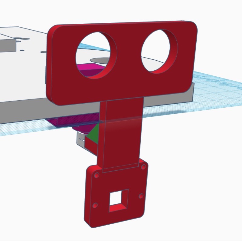
After toying with the idea of reverse Ackerman geometry for a while, I concluded any kind of linkage between the two wheels and the front sensor would interfere with the steering. Then I chanced upon the my current chassis where the previous servo motor was attached and it light up a 💡. Why not use the front servo to control the Ultrasonic sensor and the camera. The Ultrasonic sensor would work for the maze follow while the camera could be used for ball follow in Over the moon or even line follow for speed test.
The new Camera + Ultrasonic sensor mount I came up with looked like this:

The Ackerman Steering assembly
Next came the actual steering assembly.
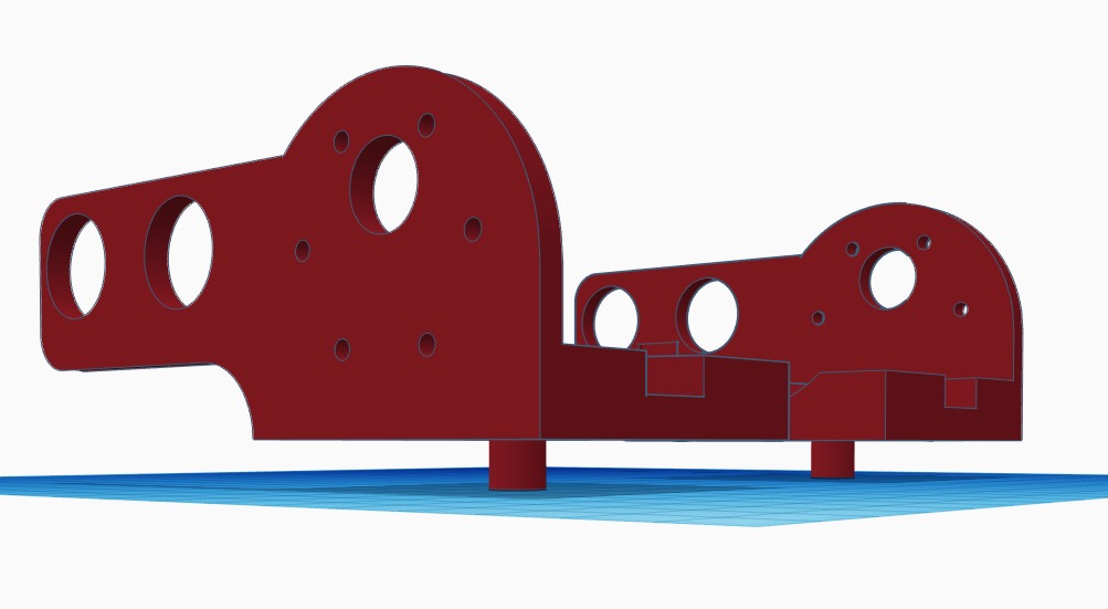
I started by splitting the motor holders into two, left and right.

Notice the two grooves carved out in the design. These are a part of the assembly that's going to help the mounts turn left and right differentially. The angle of these grooves is such that of you can draw a straight line from the center of the steering bearing straight down to the middle of the rear axle. This is called "Full Ackerman".
The Servo and the linkages
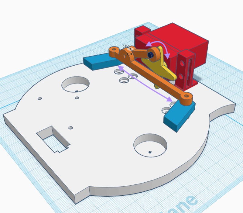
The steering servo now moves to the middle of the of the chassis such that it's motor is aligned in the center.

The links assembly of the steering looks like this:

The blue links go into the grooves cut out in each motor mount as shown in previous image. The long horizontal link goes left and right. Since the blue links are lock on to the motor mounts, they pivot on the bearings. See image section below.
The smaller orange link is coupled to the steering horn so that motor horn pushes it right or pulls it left when the motor moves.
None of the joints seen here are fixed, all of them are movable joints.
How will the mounts turn?
The mounts actually have a tiny pivot at the bottom as seen below. It's 7mm in dia so it provides a snug fit on the bearing's inner ring.

The idea is inner ring of the bearing will be with the motor mount and the outer ring will fit on the chassis. They will be joined by a nut and bolt arrangement down the middle.
When it's all put together it looks a bit like this. [Image]
It works!
The first cut of the steering links were a little too loose so, while it worked, the differential caused a large dead spot one way.
Still looked pretty neat and I was excited:
We have steering people! Thanks in part to @bohblesku for the warning about the servo size. Lots of tuning and part redoing remains but I think this will take the load of the entire bot! We’ll check that next! #excited #robots #PiWars pic.twitter.com/zTHXZp9k0g
— Pi of things (@piofthings) 26 November 2017
The next iteration was much better.
Ooh yeah! Steering with wheels on the ground! Now I need to firm up the chassis! #PiWars #thunderborg #ultraborg pic.twitter.com/Bj43XsW9TL
— Pi of things (@piofthings) 1 December 2017
Notice how the angle of the wheels are different as they turn. The wheel on the outside turns less than the wheels on the inside. That my friends was a crude implementation of Ackerman Steering Geometry!
With that sorted, time to wire up the motors and Ultrasonic sensors so that we can start work on autonomous movements.
