Putting together a digital photo frame using a Raspberry Pi
2018-1-12
By Sumit Maitra
I have had this idea of a portable Pi tablet style computer for a while. My first touchscreen purchase was specifically for building such a portable Pi device. However the driver for the WaveShare display went bust and with that it got consigned to my heap of "Todo later" projects.
Around Boxing Day last year (2017), when there were some neat discounts available for official RaspberryPi hardware, I managed to snag the RaspberryPi official 7" display, with the intention of converting it into a quick Picture frame for my parents as their Christmas gift. Little did I know how badly I had miscalculated the effort required.
This is a very costly and roundabout way to build a rather small digital photo frame. If you want only a photo frame with images stuck in an SD card there are lots and lots of much cheaper options, that give you a much bigger screen. Consider yourself warned.
The hardware
- Raspberry Pi 3
- Raspberry Pi Original 7" display
- 16 Gb micro SD card
- RaspberryPi official power supply (2.5A minimum)
- Pimoroni OnOff Button shim
Adafruit Powerboost 1000C3.7 Lipo from Pimoroni/Adafruit8 K Ohm and 22 K Ohm resistors- 3D Printed case
- Loads of M2 nuts and bolts 10mm to 12mm
- 1 tactile push button switch
- Some proto-board/perf-board and a hacksaw to cut them to size
- 12" long Raspberry Pi camera/display flat cable
From the workshop
- A low powered or manual drill with a 2mm drill bit
Why are some of the items struck out? Well, I started with them in my initial design but had to drop them later. You will see some pictures that include them, so just a heads up. I'll also explain why I dropped them.
Designing the enclosure
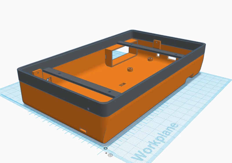
First challenge was to do the 3D Design. This took the longest. But if you are going to try this out yourself, you don't have to start from scratch all the models I built are available on Tinkercad (under CC-BY-SA 3.0 license)
The design is split into two parts.
- The top part that holds the display screen
- The bottom part that houses the Pi and the switch

The angled side is the bottom and the frame slants back slightly as it sits. Initially I thought it wouldn't stand on its own, but it turned out rather stable.
Printing the enclosure
Printing the enclosure was a challenge in itself and unless you have a print bed that's greater than 220mm on one side you'll have to split the bits up. I have a separate design for the each of the broken down bits.
For the top-frame I designed a nice overlap so I had enough surface to apply the glue to.
For the bottom bit, I cut it straight but kept it un-equal so the join wouldn't be down the middle for both the pieces. For some reason I concluded it wouldn't look good or be not strong enough. Both were pretty unfounded I think.
Assembling the components
As seen from the hardware list above I had plans to power the project via a wall wart as well as battery, hence the PowerBoost 1000C. The PowerBoost was supposed to be at the left bottom corner and the RaspberryPi is planned to be on the right. In middle was space for the OnOff button shim and a 1200 mAh LiPo pack.
Since I yanked the PowerBoost and the LiPo at the last moment, the OnOff button shim's input moved had to be moved to where the PowerBoost originally was. Also the on off shim doesn't have and screw holes. I worked around by pinning it on a slightly bigger piece of Proto board and bolting the ProtoBoard to the chassis.
The shim comes with a breakout for an external tactile button (On when pushed, off when released) . I passed the header pins from under, so it brought together protoboard and the shim. Then I soldered it on the shim, took out the plastic separators and soldered it on the ProtoBoard. Thus the board was now a nice extension of the Shim.
I soldered the a set of headers on the shim and connected to the GPIO pins as they were intended (if the Shim had been soldered straight in). Point to note, use as small a jumper cable as possible to reduce current drop.
The new official displays only need the 5V and GND pins connected from the Pi. The touch information is now passed via the DSI cable connector. So I powered the display via the other free 5V pin on the Pi header and a GND pin.
The software
Once you have the 3DPrinted components the hardware is easy enough to assemble, the software I built wasn't too complicated.
It is a simple Electron JS app I call Cloud Nine.
It connects to a specified Azure blob storage using a shared access key (be very careful here, don't use account key that will give anyone with access to it, read/write access to your blob storage).
Normally people build Electron Apps using React, but I am rather old fashioned so I use RequireJS and Knockout. It is styled using the ubiquitous Bootstrap style library and the core functionality uses Bootstrap slide-show component.
Since I was in a terrible hurry to get it out of the door, I haven't tested it for scale so if you try to load a million images on this, it might run out of memory. I'll add a scalability note once I've uploaded all my images to the Blob store (and tested it myself.)
Also note an immediate optimisation I have in mind is to resize the images. I was using lwip node module earlier to resize images on another Electron app I built but lwip seems to be broken at the moment. So, either I'll have to fix what's broken or find a different library. Also I plan to throw Azure functions into the mix at some point.
The code is open source, feel free to have a go, file bugs or send PRs.
Here is what it looks like: 
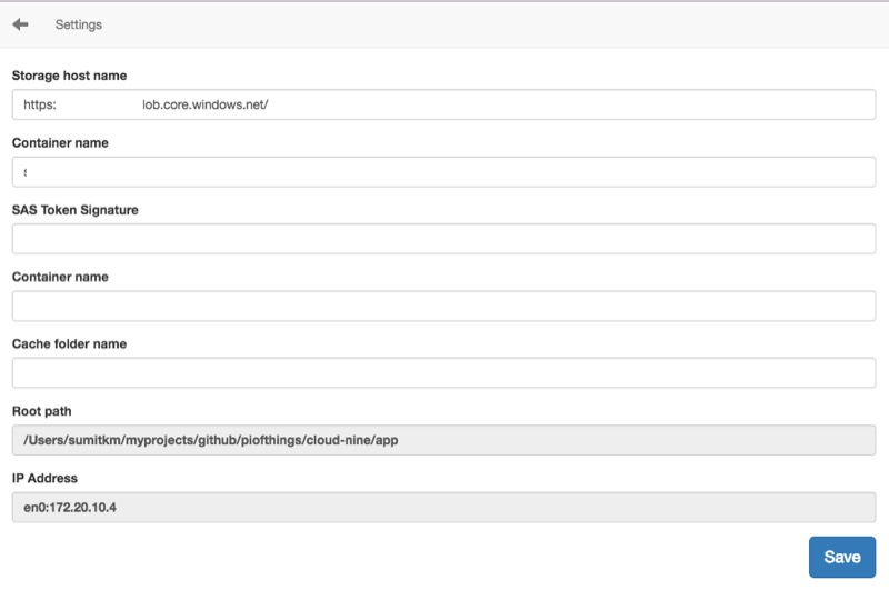
The Settings page has some basic settings to get you to connect to the Azure blob storage.

The settings are mostly Azure blob storage related. If I get around to doing other stores I'll update the UI appropriately. Maybe start with a picker of supported stores.
Refresh, initiates a request to pull down new files. Ideally I would like this to be automatic on a timed poll. Haven't managed to get to it yet.
The close button closes the app and returns you to the Desktop.
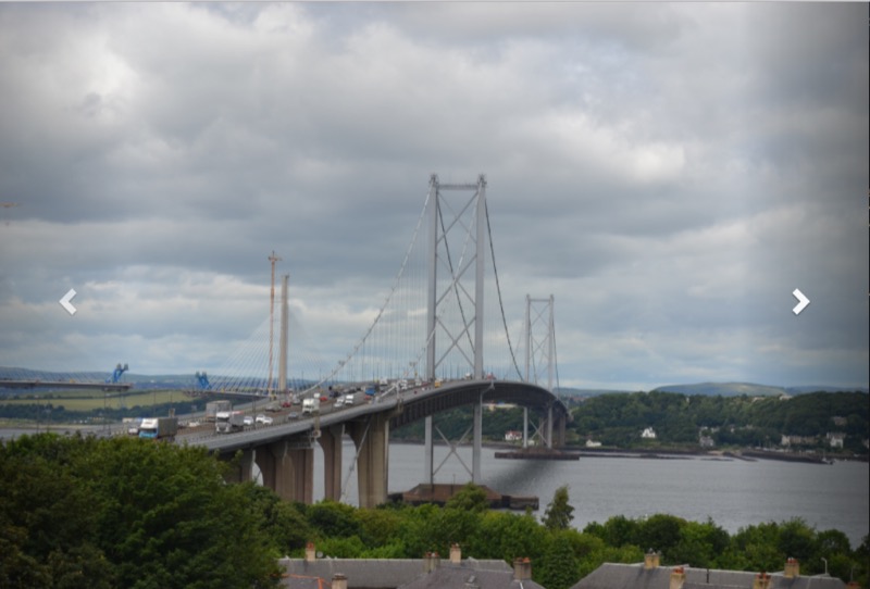
Finally the slide-show initiates the photo-frame mode where is loops through the images that it has downloaded infinitely.

(That's an image don't click on the navigation arrows :-)..)
Tapping on the screen bring up the navigation arrows and the top navigation bar. The navigation bar vanishes after a few seconds.
Next steps
Currently I don't have a release plan or for it and Electron doesn't seem to have the integrated updater for Linux. Once I've sorted it out I'll start releasing packages and installers on all platforms Electron supports. Till then feel free to clone and run.
Special mention
Many thanks to Phil Howard aka @Gadgetoid of Pimoroni whose prompt answers on OnOffShim helped me ship this off with my parents on time. Phil runs pinout.xyz - the definitive reference of RaspberryPi HATs and pHATs GPIO pin compatibility with the Pi. Phil has a Patreon page, go support him if you can!
Here are a few images that show the making of the photo-frame (that's a carousel you can click left or right).


