Update 6: Pan, tilt, see... Vision challenges in progress...
2018-3-12
By Sumit Kumar Maitra
Another weekend... and yet another, smaller than expected turnaround... but we have made progress. As mentioned in the last post, I have been racing to complete the Pixy camera integration before I finalize the routing logic for Pi-o-steer. I thought this week would be it, but we had a scope creep... we ended up designing, 3D Printing and assembling a full Pan-Last mechanism. On any other day I would have considered that a big achievement but in the big scheme of things it wasn't as big.
KYS (Know your Servos)
The week started off with me receiving the continuous rotation servo from Pimoroni among other bits and bobs. The idea was to swap the 135 degree motor that came with the original Pan-tilt-mechanism (from Adafruit/Pimoroni) with the continuous rotation one, with the intent of driving the motor 270 degrees left to right so that it gives the bot a good enough field of view to see all the 4 balls for the Over-the-Rainbow challenge. However, it turns out I don't know my servos well enough. Micro continuous rotation servos like the FS90R behave more like DC Motors than like Servos. You can't tell them to turn by x degrees. Instead you set a speed and turn them on and off. Based on speed and duration that you left them on, the servo with turn by y amount. Needless to say this increases the work (read maths) that needs to be done to manage the Servo. Here is a thread I started on PiBorg's forum as I bumbled through the about 'discovery'.
Upgrade again, a 270 degrees servo, coming up!
Faced with additional software development time, I once again did the time vs. cost and went with saving time than cost. So got myself a nice 270 degrees rotation Servo from Amazon. It's the same make as my steering motor and since the steering motor worked without an issue I just went with it blindly.
Now this is a full size motor and reto-fitting it in the existing pan-tilt mechanism was not possible. I briefly held the hope that I would need to change the bottom bit only, but once I had the new motor in my hand, that option vanished quickly.
When you have a hammer... (err... I mean 3D Printer)
Luckily I already had a to-scale model for my previous driving motor as well as the first micro servo that I tried to use for steering. This meant I could have a go at the design straightaway. Taking 'inspiration' from the design in front of my I came up with this.
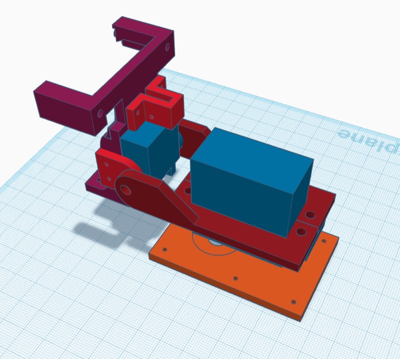
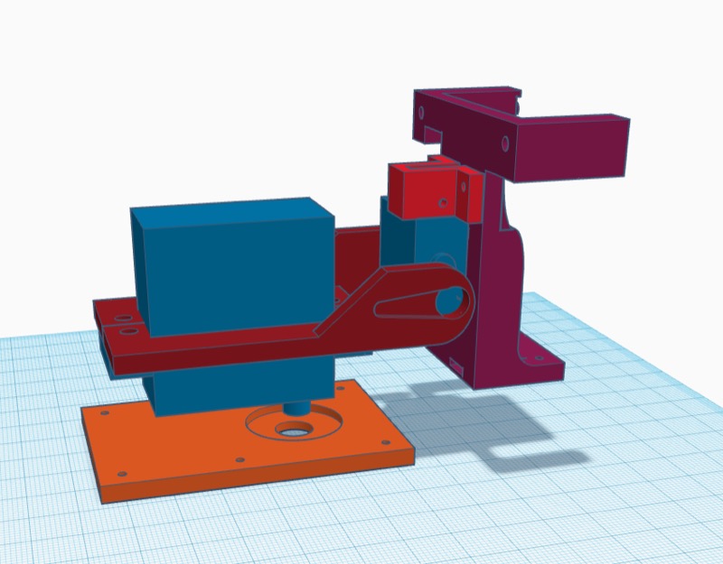
The design implies the big 270 degree motor is downward facing and bolted to the base plate (floor). So when the motor is turned the whole assembly tied to it turns. Rest of the tilt mechanism is tied to the big motor.
- The blue bits are the two motors these are not printed, rather placeholders for real things.
- The maroon parts clamp to the pan motor. They are split down the middle for assembly purposes. The right has side piece has the hole and cutout to hold the tilt motor. The tilt motor's spindle is also bolted down, so when the tilt motor is turned the whole motor turns up and down.
- The red bits tie the Tilt motor to the Pixie Cam holder.
- The violet part is the Pixy cam holder.
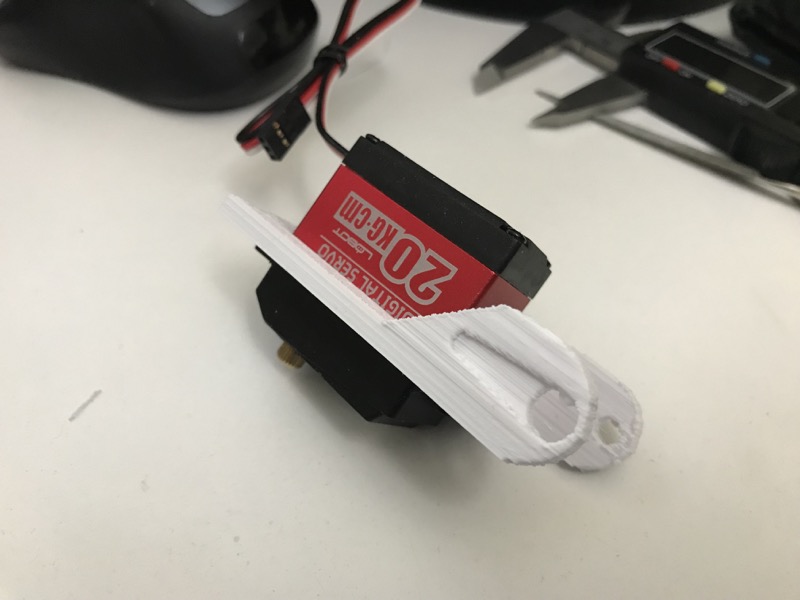
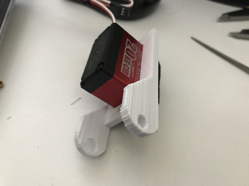
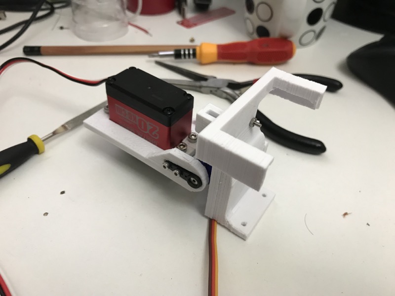
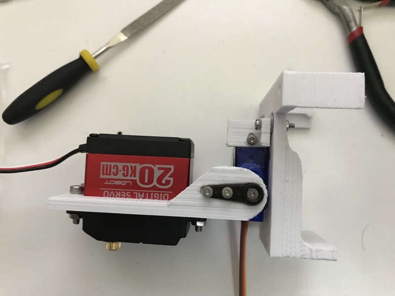
Here are some more pictures of the assembly process and assembled unit.
Last but not least, here's a video of the mount in action.
Right then, we can crane our ‘neck’ 270 degrees to see what’s behind us (mostly). Up next, heading that way… #piwars #OverTheRainbow Also, that’s custom pan-tilt had driven by @Pi_Borg #ultraborg pic.twitter.com/nFLKoKDM4e
— Pi of things (@piofthings) March 12, 2018
Up next, getting the bot to go where it detects the ball.

